
SERVICE MANUAL
|
|
Electrical Repairs
Calibration
|
|
|
||
|
|
|
|
|
Technical Data |
||
|
|
||
Continuous operation, with intermittent
use.
Electronic system is
set to hold a minimum 121°C for 16 minutes
(except 210006), 126°C for 11 minutes or 134°C
for 3.5 minutes when loaded with instruments.
On model 210006 the
electronic system is set to hold 121 °C minimum,
for 18 minutes when loaded with instruments.
All sterilizing
times incorporate a safety margin between 0.5 and 1
minute depending on the operating temperature.
Nominal operating
pressures are 1.05 Bar (15 psi)
at 121°C, 1.6 BAR (23psi) at 126°C, and 2.2 BAR (32 psi) at 134°C.
Minimum vessel burst pressure is 7.8 Bar
(115 psi).
Safety features
·
Pressure release
valve
·
lid pressure
interlock
·
Gasket offset
device (prevents pressure build up if lid not
closed correctly)
·
Body thermal fuse
·
Boil dry detector
·
Gasket extrusion slot for pressure relief
·
End of cycle buzzer.
·
Bi-metallic air
bleed device fitted.
Pressure and temperature gauges available on some models
(refer to price list).
|
||
Mechanical Repairs |
||
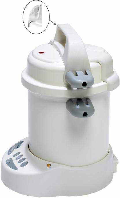
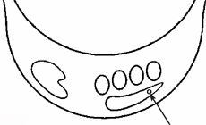
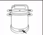
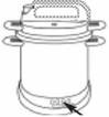
STEAM RELEASE VALVE: Part # 219711 for Prestige Classic 210006
|
Fig 1. |
|
Circlip in
valve handle. To replace the circlip, remove the decal and push up the valve
stem. The circlip may now be removed / replaced |
To replace this valve, remove lock nut from inside the lid with a 13mm spanner
and lift out complete valve (Fig.1). Replace the valve with new one. Ensure cutouts in the aluminium valve body fit into notches on top handle.
Always replace the seal when refitting the
valve. These locate
the valve in position.
Tighten nut to 10Nm.
PRESSURE INDICATOR:
To remove this indicator, locate M16 hexagonal nut in a socket and use the
specified tool to undo the red cap.
(For tool kit see 6:
Tools and Test Equipment).
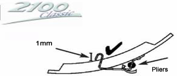
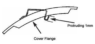
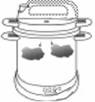
GASKET OFFSET DEVICE:
The gasket offset device (GOD spring) is a very important safety device. It ensures that if the lid is incorrectly
fitted pressure cannot build up.
This device must be inspected monthly
To work correctly the spring must be firmly
riveted to the lid. It must protrude on the inside of the lid, past the flange by a minimum of
1mm (with gasket removed).
See figures 3 and 4.
A new spring cannot be fitted without the
correct factory
equipment, spring and riveter.
If the spring or rivet is damaged a new lid
must be fitted.
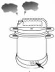
Procedure to correct GOD Spring setting
If the limits are outside the specification, then the GOD spring has to be adjusted using long nose pliers.
Fig 2.
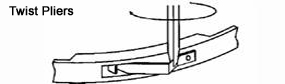
Ensure the lid is flat and stable and apply the pliers vertically. Locate the pliers onto the back edge of the spring and twist inwards carefully. Do not buckle the spring. Check visually and measure the distance again.
Fig 4.
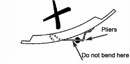
Fig 5.
SIDE HANDLES, TOP HANDLE and STEAM DUCT:
Side handles are held in
place by M5 securing screws.
To remove the top handle, first remove the steam release valve as previously described, (Fig 1.)
Unscrew the side handles.
Once the top handle is removed the steam duct can be removed by releasing the two retaining pins.
After removal the steam duct will need to be replaced with a new one. Insert
the two pins into
the appropriate holes in the lid and secure in place by melting the ends using
the tip of a hot
soldering iron, ensuring that the pins cannot pass back through the holes.
Replace new side handles and top handle following the reverse of the
sequence previously
described.
New seals must always be used when refitting the top handle, steam duct and steam valve.
Side Handle Part # 219696 for Prestige Classic 210006
Top Handle Part # 219698 for Prestige Classic 210006
AIR BLEED DEVICE:
To remove, first take off steam release valve and top handle as previously described
(on the 210134 and 210006 you need to remove the steam duct as well). Break off retaining clip
and throw away old assembly. (Never re-use assemblies). Fit new air bleed device with ‘O’ ring, push
into lid hole, place washer over valve stem and force ‘push fix’ down to lock the device in position.
Use special tool to push clip over air bleed device spigot.
(For tool kit see 6: Tools and Test Equipment).
Air Bleed Device Part # 219202 for Prestige Classic 210006
LID GASKET:
Simply extract the old gasket from the lid flanges and replace with a new one.
Only genuine Prestige Medical parts to be fitted.
Note: No lubrication is required for the gasket.
However, if the lid is difficult to put on, Vaseline (petroleum jelly) can be
lightly smeared around the edge
and
underside of the body flanges.
Lid Gasket Part # 219500 for Prestige Classic 210006
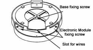
BASE MOULDING:
Place body on a flat
surface upside down. Then remove the three ‘posi’ screws, which hold the electronic
module in place
Lift out heatsink to remove module from base moulding. Disconnect the
display ribbon cable connector.
Next, remove the earth wires from the body stud, then loosen the nut for
the thermistor wire clamp (All M5 size).
Fig 6.
Disconnect the push on terminals from the
wiring of the base and
the heater element.
The electronic module is now free (Do not
remove the thermistor fixing nuts).
Next, remove the
fixing screw M5, in the centre of the base moulding and pull off the base moulding complete whilst feeding the module between the moulded support
legs.
Replace the base moulding with a new one in reverse order. DO NOT OVER TIGHTEN SCREW (2.5Nm
torque). Check to ensure the silicone caps are in position
Make sure no wires are trapped between the base and the body.
Ensure the thermal
fuse is in contact with the base, making sure the white
putty supporting the thermal fuse is replaced 1
Refitting is in reverse order of the above. The M5 nuts should be tightened to 1 .4Nm. Note:
1.
Each earth wire must be fixed to the body
stud with a nut (2
wires and 2 nuts).
2. An earth insulation test must also be carried out
3.
Apply new feet if necessary.
4. Do not forget to transfer the rating plate.
5.
Ensure that the wires
between rear mains inlet and module are
retained in the location slots provided.
6. Always check that the push on connectors are tight and do
not show signs of overheating.
Base Kit Part # 219665 for Prestige Classic 210006
|
||
Electrical Repairs |
||
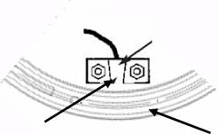
THERMAL FUSES:
The thermal fuse is in the base moulding, to gain access to this
part, remove the base as previously described.
The thermal fuse is in the brown wire and
must be replaced as a complete assembly with wires and terminals
(Fig 7).
Do not
replace the fuse only, as this cannot be reconnected to the
brown wires without a proper crimping tool.
Thermal Fuse Part # 219667 for Prestige Classic 210006
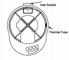
MAINS INPUT SOCKET:
Remove base as previously described and remove push on
terminals from input socket (Fig.7).
Remove fixing screws from the socket.
Fit new
socket and refit base in reverse order.
Always check that the push
on connectors are tight and do not show signs of overheating.
ELECTRONIC CONTROL (COMPLETE):
Place body on a flat
surface upside down. Then remove the three posi screws, which hold the electronic
module in place
Lift up the control module (complete) and disconnect the push on terminals from the wiring of the base and element (as previously described).
Disconnect display ribbon cable. Remove thermistor
wire cleat. Remove 2 x M5 nuts on earth stud.
Remove both M5 thermistor
pocket retaining nuts. Control module may now be removed.
Note:
1. Clean away all the silicone heat sink compound.
2. When refitting thermistor pocket, apply compound to base of the body centrally between studs (small
quantity of compound - 3mm bead size).
Mazak pocket must be pushed towards element. Excess compound must not touch the element
- See Fig 8.
Fig 8.
Position Thermistor pocket to create gap - min O.5 mm; max
1 mm - between pocket & element
3.
Refit module in
reverse sequence for removal including
replacement of white putty under the thermal fuse.
4.
The tightening torque for M5 studs is 1 .4Nm.
6. Always check that the push
on connectors are tight and do not show signs of
overheating.
LED Switch BOARD:
Follow directions for
removing Electronic control as per‘base moulding removal’.
Remove the three ‘pozi’
screws, disconnect the ribbon cable and take
the LED Switch board out.
LED Switch Part # 219585 for Prestige Classic 210006
110 Volt Module Part # 219590 for Prestige Classic 210006
PRESSURE GAUGE & TEMPERATURE GAUGE:
To replace a damaged or faulty pressure gauge,
the 1/4
BSP nut must be removed.
To replace a
damaged or faulty temperature gauge the 3/8
BSP nut must be removed.
The gauge to
lid seal is provided by a knife edge machined onto the gauge boss. On a stainless steel lid an aluminium washer is required to complete the seal
The lid must be inspected to ensure there is no damage in this area.
There should be an unbroken indented ring around the
hole.
Care must be taken to
ensure the knife edge seat on the replacement
gauge is not damaged. On stainless steel lids
always replace the aluminium washer when
replacing a gauge. The gauges must be correctly
orientated (nuts to be re-tightened to 35Nm.)
Note: Entry port may
be removed by undoing the locknut. Ensure
knife edge seal is not damaged and that there is a
continuous seal indent in the lid.
THERMOCOUPLE ENTRY
This device consists
of connector body, locknut (25mm across flats)
and a 3/8 BSP plug (fitted with an ‘O’ ring.)
This assembly utilises
a knife edge seal to lid.
The purpose of the
entry port is to enable a qualified engineer to fit a
thermocouple pressure probe to check the calibration of the autoclave.
Thermo Port Part # 219750 for Prestige Classic 210006
|
||
Calibration |
||
To calibrate, lift the start switch decal at the narrow end, place a potentiometer trimmer into the temperature
adjuster (Fig.9),
Fill to water level
with de-ionised/distilled water (0.75L). Put
on the test lid with pressure gauge and digital thermometer connected. Then open
the vent valve.
Place the furniture appropriate for the model
in the chamber.
Press start
button.
Note: Pressing the Start Button when the Yellow sterilizing
light is illuminated will automatically set the
electronic timer to zero and re-start the sterilizing cycle timer.
Orange heating light should be on.
When temperature of 105°C is reached, close valve.
After about 10 minutes from the start time, the sterilizing light should be
lit with the heating light pulsing.
When the sterilizing light has been on for 5
minutes the temperature should be stabilised at
between:-
121°C Autoclave 125.5°C to 126.5°C
126°C Autoclave 128.0°C to 129.0°C
134°C Autoclave 136.0°C to 137.0°C
Note: On
the 134°C autoclave it will be necessary to press the start button after 2 minutes to reset
the sterilizing timer.
If this temperature is too low, turn the pot
trimmer clockwise
one click at a time to increase the temperature by 0.5 to 1.0°C, allow 1 to 2 minutes
for the temperature to stabilise on thermometer.
Press start button after each adjustment to
reset timer.
If the temperature is too high, turn the pot
trimmer anti-clockwise
one click at a time, open the steam release valve for 1 to 2 seconds to drop the temperature quickly.
Note: It is important that the temperature is dropped below
target value before vent valve is closed.
When the temperature is stable, switch of and vent with the steam release valve
for 1.5 minutes until the temperature
is 105°C to 110°C, close the valve and switch on and start another
cycle.
FINAL TEST FROM COLD:
Check water level, put furniture in the chamber together with a sterile indication (T. S.T) strip.
Fit product
lid, close vent valve and start a cycle. Check the heating light, note the cycle time
(3.5 minutes, 11
minutes, 16 minutes or 18 minutes minimum depending on
sterilizing temperature – see page 2 for details).
Check that the sterilizing light goes out after
cycle complete light comes on.
Buzzer should sound when the cycle ends.
When cooled down, check the TST indicator strip has changed from yellow to
purple/blue.
Note:
1. If the autoclave is in an ambient temperature
of 0°C or less, it will not start a heating cycle. In the event of this occurring, warm
up autoclave by moving to
another room or add hot water.
(Don’t forget to empty and refill with de-onised
/ distilled water).
|
|
|
|
Fault Diagnosis |
|
|
|
 |
Steam or water leaking from the lid of the unit |
Worn or dirty gasket Incorrectly fitted lid |
Wash gasket - replace in lid Remove lid Part # 219738 and replace |
 |
Excessive steam or water leaking from the depressurization valve |
Valve in open position
Worn spring in valve
Blown Fuse Defective Socket
|
Close valve Replace Valve Part # 219711
Check/Replace Fuse Part # 219667 Check power to Socket Part # 219235 Ensure Lead Connected
|
 |
TST Strip not changing color. |
Unsatisfactory Cycle. |
Check expiry date on TST Strip Box Part # 259277 Disconnect from Mains. ReConnect & Repeat Cycle. If still unsatisfactory arrange service. |
|
Red Fault Light Flashes |
Insufficient Water. |
Allow unit to cool & refill to correct level. Disconnect from mains. Reconnect & repeat cycle. If the water level is okay disconnect from mains, reconnect & repeat cycle. If still unsatisfactory arrange service |
 |
Green sterilization light fails to illuminate |
Disconnect from mains, reconnect & repeat cycle. If still unsatisfactory arrange service |
|
|
|
|
Tools and
Test Equipment |
|
|
|
The following tools will be required in servicing/repairing
the autoclave:
STANDARD TOOLS:
Torque wrench
(10 to 45 Nm)
Torque wrench
(0.7 to 1.4 Nm)
No 1 Pozidriv
No 2 Pozidriv Socket 26mm Socket 20mm Socket 18mm (long
reach)
Socket 16mm Socket 14mm Socket 13mm Socket 8mm (long reach)
Various socket adaptors to mate up with torque wrenches
Long nose
pliers
Sharp knife
SPECIAL TOOLS:
available as a tool kit, reference Part # 219287 for Prestige Classic 210006 . Please call
for full details and cost.
M5 nut runner
Air bleed
push fix
Potentiometer trimmer (flat bladed jewellers screwdriver).
Pressure indicator driver
TEST EQUIPMENT:
Continuity tester
Temperature
probe (3mm o/d)
Temperature recorder/ indicator
N.B Ensure all your test equipment has a current
calibration certificate.