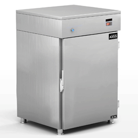
Large Sterilizers, see below for sizes

| |
SPECIFICATIONS
ELECTRICAL
All
operator cycle designations are reduced to 24 volt AC operation.
Normal electrical functions are operated at 110 volt AC. The 24
volt AC operation reduces operator exposure to electrical power.
Most
control components shall be "plug-in" style which enhances service
if it should be required.
|
Sterilize (Cycle) and Dry Timers shall be automatic reset type which
allows the operator to visibly acknowledge the preset time as well
as the elapsed time.
A
main wiring terminal strip allows easy checking of electrical components
if required.
All
electrical connectors and wiring shall be numbered and color coded
for ease of service.
Cycle
sequence shall be easily monitored through the use of rectangular
indicator lamps showing each phase of cycle operation.
A
"DOOR LOCKED" light shall illuminate when the chamber door is properly
closed.
**A
"LOW STEAM PRESSURE" light will illuminate and the cycle cannot be
initiated if a low steam pressure situation exists.
All
operation functions shall be initiated through the use of various
solenoid valves which shall fully control the cycle of the sterilizer.
Cycle
selections shall be designated by the operator by a single press of
a button, and the cycle selector shall illuminate to allow other personnel
to realize a cycle has been selected and started.
If
electrical AC power is unavailable, steam will not enter the chamber.
If electrical power is interrupted, the autoclave shall automatically
vent all pressure from the chamber, allowing the chamber door to be
opened. Simultaneously, the unit shall reset all cycle functions.
When power is restored, the cycle selection must again be designated
by the operator.
The
entire electrical circuit shall be protected by a manual reset type
circuit breaker, rated for the maximum acceptable amperage for the
electrical components used.
All
electrical components shall be Underwriters Laboratories approved
and/or listed, as necessary.
Temperature
control and documentation shall be assured with the use of a United
Electric Model 650, 61' inkless recorder, mounted in its own cabinet
box and secured to the control panel.
PLUMBING
All
piping shall be rigid brass with threaded connections, with the exception
of pressure sensing piping, which shall be 1/4 " O.D. copper with
flair or compression connections.
All
solenoid operated valves shall be of one manufacturer, and rated for
a minimum of 50 psi operation.
All
plumbing components shall be installed with brass union connectors
to allow ease of service or replacement, if required.
*
* Optional
All
manual supply valves shall be "ball" type, actuated with a manual
handle.
Pressure
gauges for supply steam pressure, jacket pressure, and chamber pressure
shall be mounted in such a way that the operator can easily monitor
variations.
The
vessel shall be protected against high pressure with the use of a
safety valve rated at the maximum operating pressure of the vessel
as stated by the original manufacturer, and shall not exceed A.S.M.E.
standards.
VESSEL
The
existing vessel shall be hydrostatically tested at 1.5 times its rated
working pressure to assure long life of the vessel.
The
interior shall be cleaned with the use of a fine glass bead, applied
under pressure, to remove existing discoloration normally found on
the inside chamber walls.
The
exterior shell shall be painted with high heat temperature, rust retardant
paint.
The
exterior shell shall then be covered with 2' thick, foil backed insulation
to reduce ambient heat normally released from the vessel.
The
door for the vessel shall be refinished and/or rebuilt, as needed.
CONTROL
PANEL
The
main control panel shall be fabricated with .125" thick aluminum.
All designation lettering shall be engraved into the panel and paint
filled, for long life and durability.
The
control panel shall be mounted to a fabricated stainless steel primary
frame on top of chamber, and shall tilt down at the operator for ease
of visual operation and a pleasant cosmetic appearance.
The
main control panel shall be hinged for easy access for maintenance
and calibration purposes.
GENERAL
All
stainless steel and painted surfaces shall be refinished as needed
for a "like new" appearance (not applicable to NEW sterilizers).
Complete
calibration and testing shall be performed prior to shipment.
Upon
completion of installation, Alfa shall provide complete orientation
and demonstration of the sterilizer.
Installation
is included only when so quoted. Any structural or cosmetic repairs
to existing walls, floors, ceilings, etc. shall be the responsibility
of the customer.
Also, if you need a refurbished sterilizer, we have a several options ...
Refurbished Large Amsco Autoclaves and Sterilizers
AutoClave Installation Overview
General Guidelines
Please note this is a condensed version of what is needed for proper operation. Complete installation and user instructions will be provided with the autoclave. It is further recommended that you contact the factory for a list of authorized service representatives in your area.
I. Setting the unit in place
A. Service access should be 18 inches each side, 18 inches in the back
B. Utility connections should be in the same room within 5 feet of unit
II. Plumbing Connections: unit, generator, waste cooling, steam, drain, and boiler blow down
A. Cold Water, 45 - 65 psi dynamic, 1/2" or 3/4" with shut off valve and union
B. Generator, hot 45 - 65 psi dynamic, 1/2" with shut off valve and union
i. Preferred: R.O. quality (< 1.0 MegaOhm)
ii. Next Best: Softened (0 - 17 ppm or < 1.0 Grains/Gallon)
C. Direct Steam, 50-80 psi dynamic, 3/4 inch with shut off valve and union
i. Drip leg (with trap) 18 inches under steam connection, supplied by facility
ii. Steam should be condensate free between 97% to 100% saturated
D. Waste connection needs 2 inch air gap at 3 inch floor drain
i. Most units after 070108 serial number, 2" nominal copper unit drain
ii. Some units 1" nominal copper unit drain
E. Safety valves to be piped 5" above the floor. Check with local codes.
III. Electrical is job specific
A. Generator disconnect by unit, follow local codes, specify voltage, phase and amps
B. Unit control PB series, 120 VAC, 60 Hz, Single Phase, 20 amp, 3 prong receptacle
C. Unit control MC Series, 120 VAC, 60 Hz, Single Phase, 20 amp, 3 prong receptacle
D. Vacuum Pump, disconnect by unit, specify voltage, phase and amps. Follow all local codes.
E. Water booster pump for ejector, specify at location
F. Water feed pump, 1/3 hp, specify at location
Note: The above information should be used as a reference only. Your facility may have specific requirements. In addition, the factory and an authorized service representative should be contacted for special needs (i.e. bio-seal, double door, stacked unite, etc.).
Waste Water Cooling:
The device used to maintain a tempreture no greater than 140F at the house supplied floor drain is not electrically controlled. The drain tempreture is controlled mechanically, thus preventing tempretures from rising too high even in blackout conditions.
Astell Autoclaves

Click here for price.


